A complete NEC electrostatic accelerator system consists of:
Each system’s component configuration and layout are customized to meet the user’s specific needs.
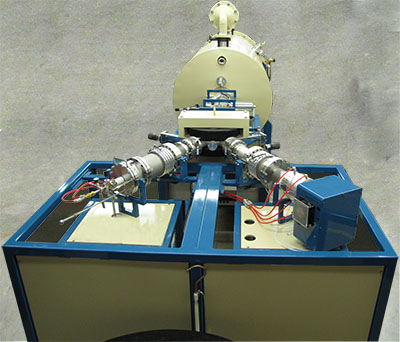
Injectors begin with one or more ion sources that produce positive or negative ion beams. The source is typically followed by bending magnets or electrostatic analyzers that focus the ion beam into the accelerator. Diagnostic equipment and other focusing elements are also an integral part of the injector. Various configurations can be used depending on the user’s requirements. Detailed information regarding our various available sources can be found in the sources section.
Single source injector with NEC Alphatross source
Dual source injector with NEC SNICS (left) and Alphatross (right) sources, without safety cages
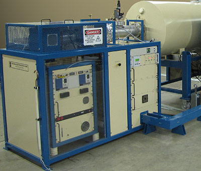
Electrostatic accelerators work on the basic principle that negative ion beams are attracted to a positive terminal and that positive ion beams are accelerated away from a positive terminal. Decades ago, charging belts were used to create a high voltage terminal in air. These belt systems were known as Van de Graaff generators. As the scientific community realized the importance of creating higher voltage terminals, experiments were conducted to increase the terminal voltage by using different charging materials and insulating gases. Continuous research through the decades resulted in the creation of the most stable and reliable electrostatic accelerator system in use today: the Pelletron.
Pelletrons consist of the following:
Pelletrons can either be tandem or single ended. Tandem Pelletrons start with negative ions that go through a stripping process to break up molecules and strip electrons, thus creating the necessary positive beam. Single ended Pelletrons, on the other hand, start with a positive ion produced directly from the source inside the terminal. ![]()
After the positive beam has been accelerated, it exits the pressure vessel and enters the focusing beamline, which as the name implies, continues to focus the beam. At this point there can either be a single extended beamline leading to an analysis chamber, implanter, or other detector; or a switching magnet with up to 7 ports for multiple extended beamlines. Additional beam focusing, steering, or diagnostic components are all typically part of the extended beamlines. More information regarding these components can be found in the Products section. Like the injector beamlines, the high energy beamlines can be configured to meet user specific needs.
A post acceleration switching magnet with extended beamlines at the +/- 15 degree ports.
The accelerator system is run by a centralized control system. All accelerator parameters needed for normal operation are interfaced with the control console.
Most of the controls and readouts interface with the control console via an in-house data acquisition system known as the NEC ACT system (prior to 2009, interfacing was via CAMAC).
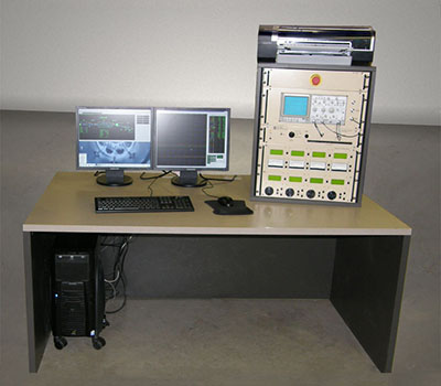
The control console consists of a dedicated computer system, assignable meters and knobs, and an oscilloscope for displaying signals.
The computer system is configured with NEC accelerator control software, AccelNET. AccelNET manages the display and control functions through a database management system operating in a multitasking environment, Linux. AccelNET is configured for each system by tailoring its database to the accelerator configuration.
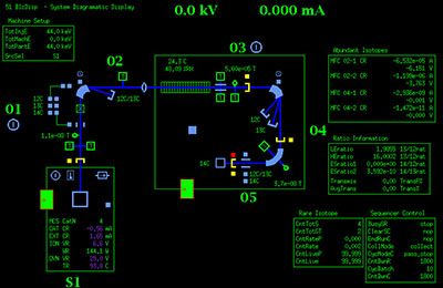 Parameters are displayed in two (2) formats: text formatted pages of parameter lists and graphic displays of the system layout. Controls can be adjusted by menu-driven restoration of stored values, increment/decrement buttons, keyboard input of the desired parameter value, or assigning the parameter to a knob for analog mode adjustments. Values of readouts are displayed on the monitor and can be assigned to either a meter for analog display or the on-screen strip chart recorder.
Vacuum and other interlocks are incorporated into the control system to protect personnel, equipment and samples.
Operators may save and restore preferred system configurations and setup preferences. This allows for an easy beam startup with little to no fine tuning needed.
©2024 National Electrostatics Corp.